Rangefinder camera needs calibration for some reasons, maybe caused by vibration, camera hit the ground, loosing screws...., anyway, if you found that the overlay images in viewing window mis-aligned or the photos are out of focus, it's time to check it out.
There is not much information about 110B rangefinder calibration on internet, the best I can find is from
Option8, master of Polaroid camera conversion/ modification.
While Byron is a little bit different from other conversion, so it provides more options for rangefinder calibration, easier and faster to finish the job.
In common case, calibration can be done by turning two screws on the back of mirror, that is...
- Focus at the infinity, then turn the screws, to align the overlay images in the view window,
- Then focus at something near, then turn the screws, to align the overlay images in the view window,
- Leave the focus between near and far to the cam curve.
Two screws adjust mirror's horizontal/ vertical movements. as image below shows, upper left screw adjusts overlay image horizontal to move left (clockwise) or right (counter clockwise) direction; Lower right screw adjust overlay image vertical to move downward (clockwise) or upward direction (counter clockwise)

It is not so easy to remember which turn to which direction, so I developed a 'Right Hand Rule' to help remembering it.

When you adjust the overlay image, and don't remember which direction screw should turn, use your right hand like this, thumb represents horizontal screw, index finger represents vertical screw, and they are now showing the direction if you turn screws clockwise!
Now back to the calibration procedure mentioned earlier, you see that no matter at infinity or at near object, only two screws available for adjustment. Isn't that funny if you align the image at infinity, then at near object requires adjustment too, won't it ruin the first alignment???
In many forums discussing about RF adjustment, people always puzzled in this dead alley, aligned image at one end, but the other is not, and then back and forth, drives people crazy, still in dead alley.
Actually there is another place to adjust the overlay image, it is the fixed screw in the middle, by loosing it a bit, you can make whole RF mechanical part turn, thus move the image horizontally, by tighten or loosing the screw, you can move the image vertically.

So there are two sets of adjustment for overlay image alignment, with one set at infinity, and other set for near object focus, thus won't ruin the previous calibration.
In theory this should satisfy all calibration required, but there is always exception. If you align both infinity and near end, but the adjustment always ruin the other one, no matter how you adjust, it just can't match both ends, in this case, it must be something wrong on cam.
This situation happens when you use the wrong section of cam curve.
If you ever read my post of
lens curves, then you knew that the relationship of distance between 'lens to focused object' (L-O) and 'lens to focal plane' (L-F) never be a linear ratio. When focusing at infinity, we set the 'lens to focal plane' as ZERO point, the least length required to utilize this lens, and an 'infinity stop' is engraved on the plate, for quickly and precisely set lens on this position.

When focus objects in distance less than infinity, rail moves and bellows extends to increase L-F distance to fulfill the requirement, as object get closer, extended distance increase more. that is, if object at about 10 meters away, maybe the L-F needs only 3mm increment, but when object at 2 meters away, increment increase to 18mm.
That explained why cam curve designed to be a parabolic curve, and if you set the wrong section, all adjustments are in vain.

Left on image shows the correct curve section on cam, infinity stop is aligned with the engraved line on cam, the ZERO point, and the curve section is match with the lens focus characteristic curve. But if the ZERO point is not aligned with the mark, then curve section must be shift, like what shows on right of image. Thus before you do any calibration, you should check if the infinity stop aligned with mark line or not.
Basic concept is clear, so we conclude the steps of calibration as following..
- Zeroing: set the lens to infinity, and make sure the mirror arm is attached with cam, on the mark line.
- Align overlay image at infinity object.
- Align overlay image at closer object.
That are all steps we will follow, then here comes the detail...
Settings

| 1. Byron camera with prime lens, ground glass panel, magnifying loupe, tripod. |

| 2. Screw drivers, one tiny flat head, one normal philips head. |

| 3. A sunny day and clear view |

| 4. Choose a contrasty object as infinity target, like a high-voltage tower, about 2 km away from my house.
What I pick is a Big number calender panel. Hang it on wall, at the same height of the tripod, parallel with camera. |
Step 1. RF housing removal

| Byron uses two screws to hold the RF housing, one is beneath the cold shoe, you need to remove tiny screw on top, and peel apart the plastic sheet to reveal the screw.
Another one is in the side plate of film chamber, this screw need a long neck driver, or you can temporary take off the sliding tooth set for easier un-screwing.
|

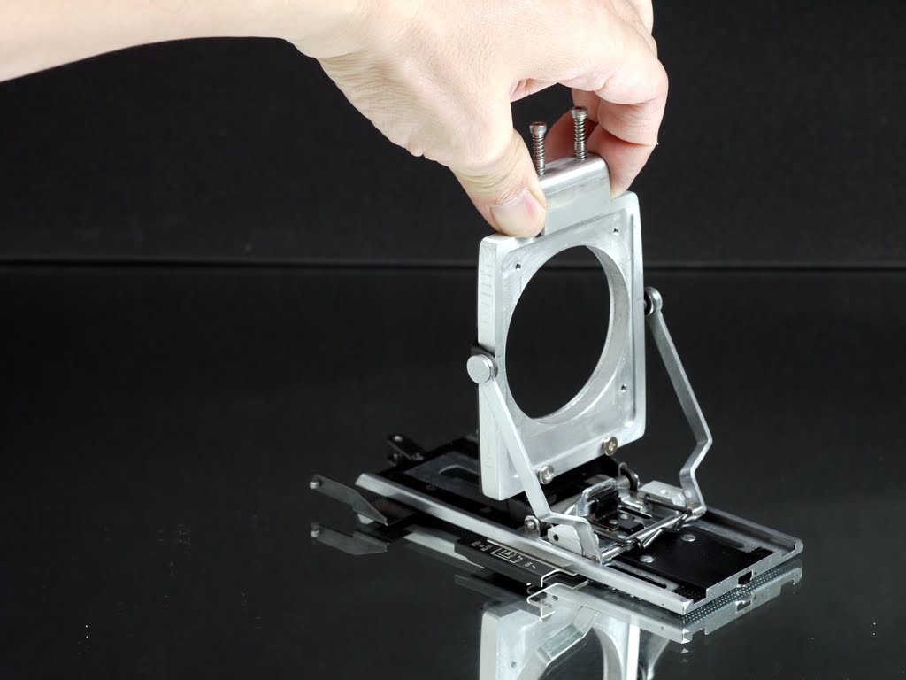
| Once two screws are removed, carefully take the housing off, and put it aside. |

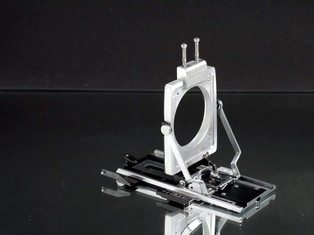
| Now the RF mechanical parts are revealed, what we will adjust later are three parts, as explained at beginning, they are fixed screw, mirror, and lens cam (from left to right). |
Step 2. Zeroing

| Now we are going to calibrate infinity end, this is no extension for rail, so called zeroing.Mount Byron onto the tripod, face the infinity object. (high voltage tower)
Mount on your prime lens, here is a Ysarex 4.7/127mm lens as example, if your prime lens is 150mm, mount it on.
Pull the front standard to the correspond infinity stop, engage the groove. Byron engraves lens length for each infinity stop, so it is easy to distinguish.
Set shutter to B, and with a cable release lock, make the lens shutter keep opening, and the aperture to full opening.
Make sure that rail is not extended, distance scale marked on infinity. You can check with loupe on ground glass panel.
Check lens cam, mirror arm should engage cam curve at the engraved line, adjust the cam by loosing locking screw if necessary.
View through the RF eye window, align the tower in the center, observe the overlaying image, do necessary adjustments, till images align with each other.
(In this step, we use two screws on mirror for adjustment)
|
Step 3. Close distance calibration
After zeroing, turn camera to close distance object (calender), adjust camera distance to object about 4 feet, about the nearest distance the lens can focus.
with loupe and ground glass panel, turn the focus knob to focus the object, after focus is set, DO NOT TOUCH THE KNOB ANYMORE! Because next step you are calibrating the overlay image based on this focus, any knob turning will need re-focus.
View through the RF eye window, align the object in center, observe the overlaying image, do necessary adjustments, till images align with each other.
(In this step, we use fixed screw for adjustment)
Step 4. Re-check, further adjustment
Both infinity and close ends are calibrated, we re-check the result by turning back to face the infinity, to see if images in eye window keep align or not.
If overlay images keep align, then the calibration is done, and you can put back the RF housing.
If overlay images are not aligned with each other, then it may caused by wrong cam curve section. By loose the cam locking screw and turn the cam a bit, to make overlay images align again.
Repeat step 1~3, make necessary adjustments, till overlay images keep align on both end.
These are steps for calibration, I hope this answer some questions about the RF adjustments.
And for Byron whose prime lens is set to 150mm, the original 127mm lens cam is replaced by custom made 150mm lens cam, they look alike, but curve is little bit different. (left: 150mm cam, right: 127mm cam)
| | Sometimes new cam needs a little bit of filing to match the lens, because each lens got its own character! That belongs to advanced fine tuning... |