By measuring rangefinder character and lens focus moving range, now we are going to combine two focus system into one-- cam, this cam will be inter-interpreting two systems, to sync each other in one. But bear in mind, one cam is synchronized with one lens, not all lenses mounted on camera.
Let's see how to do it. if there is a 150mm lens we are going to use for range-coupled with rangefinder, then before a dedicated cam is made, we need to measure the rangefinder character (A) and lens focus moving range in advance (B).
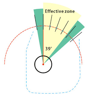
- Define radius center and zero point.
cam rotate pole radius is 2.8mm, and the zero point is 6.36mm
The light blue dash line represents 127mm cam that Polaroid originally installed.

- The mirror rotates or moves as cam outer curve changes, if the outer curve is aligned with orange dash line, which is a circle in fixed radius, then no matter how you rotate the cam, mirror will always stays at the same position.

Mirror moves as cam outer curve keeps changing it's radius (black line), outer curve across orange curve at zero point, distance between two curves is 0 at it. Outer curve is more or less radius than orange curve at other rotating angles, and according to the lens/rangefinder relations, radius changes differently.
Use orange line as reference, to point out all the radius changes. - As we measured before, cam rotates within 39° range as rail moves within 20.5mm range, effective outer curve will extended 10° more on both side, for easier installation in future.

Draw lines across the orange curve, all lines radiate from pole center, distributed every 10°, these are the reference points. - According to the lens/ rangefinder measuring data, we now locate each reference point. Let's say while we measure the rangefinder, and find out the data as follows
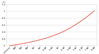
infinity 0
30m 0.04
15m 0.07
10m 0.1
8m 0.12
6m 0.16
4.5m 0.22
3.6m 0.28
3m 0.35
2.4m 0.44
1.8m 0.52
1.5m 0.6
1.2m 0.73
1.0m 0.88
0.9m 1.01
and the data was transfered into characteristic curve

Another data comes from measuring lens focus moving range
notice the y-axis in this chart, it transfer rail moving range(mm) into rotating degree, as rail moves within 20.5mm range and cam rotates within 39°, so even distributes two measurement, safely transfer two units.

find the focus distance at 10°, 20°, 30°, 39°, in chart above we get 4.45m, 2.4m, 1.7m and 1.35m. Then we back to the rangefinder chart, to locate 4.45m, 2.4m, 1.7m and 1.35m. we find that radius should add 0.24mm, 0.43mm, 0.56mm, 0.68mm accordingly. - Drag reference points on orange curve according data we just read out from charts, move them to proper distance to reflect the variations.

Then draw a smooth curve across all reference points,

- Enclose the curve with cam outline, make it a dedicated Geronar 6.3/150mm lens cam for 110B.

to compare new 150mm lens cam to original 127mm cam, you can tell the differences on outer curves. (orange curve: 127mm cam)


