Too hot these days, one of my assistant crafts master got stroke when he practiced kendo, and in Persistent vegetative state now, what a pity!
He is only 54 now.
Friday, July 29, 2011


Saturday, July 23, 2011
busy week
This week I'm gonna finish this conversion batch, forgive me for no further information on RF.
Wednesday, July 13, 2011
Some Ideas on Range-Coupled mechanism
Thinking of range-coupled mechanism these days, just came out of some ideas. No matter Linhof or Graphic, Horseman or other brands 4x5 cameras, if installed with rangefinders, all need a match cam for specific lens, otherwise no range-coupled functions available.
People are troubled when they tried to find lens and matched lens cam, the pair are rare to find these days, and the price always sky high, handheld 4x5 photography restricted by this, so called range coupled 4x5 almost vanished.
What if
Too excited! can not sleep at night.
an interesting discussion here:
http://www.largeformatphotography.info/forum/showthread.php?t=79196
People are troubled when they tried to find lens and matched lens cam, the pair are rare to find these days, and the price always sky high, handheld 4x5 photography restricted by this, so called range coupled 4x5 almost vanished.
What if
- Range coupled function needs no match lens cam.
- Any lens can be range coupled, no matter what camera used.
- Lens calibration needs no professional expert. one lens can be calibrated in 10 minutes.
Too excited! can not sleep at night.
an interesting discussion here:
http://www.largeformatphotography.info/forum/showthread.php?t=79196
Friday, July 8, 2011
Rangefinder calibrations on 110B- part6
Now there goes to final part of RF calibration.
We match the lens with rangefinder with a tailored cam, so camera can be range coupled with ONE specific lens, but that is all it can do, if you want to use other lenses, these lenses are range UN-coupled, that is, rangefinder as a pure rangefinder only, reading out the rangefinder indicates, then we adjust the lens position to match the focus.
What if we could change this ONE-LENS-ONLY range coupled camera into a multi-lenses RF camera? I thought about this for years, and many clients asked the same question also, everyone wants multi range coupled function.
Here I list some issues on this conversion as follow:
Multi cam
More than one lens range coupled needs more than one more cam, how many cam possibly be installed on a camera?
As we measured, each cam needs at least 40° of rotation, so as 360° divided by 40°, maximum we can make 8 cams simultaneously be installed on one camera, but that is too much and too complicated, I would say 3 cams is enough.
Each cam separated and distributed at every 120°, that leaves enough space and tolerance to mechanism.


Field operations
If we solve all the problem mentioned above, the final problem arise as how to operate this mechanism in field. We need a knob to rotate the cam pole, to match the lens we change, that involves changing the outlook of the RF housing, but pity there is no space for it in my opinion, best way is to re-design and re-mold the RF housing, but consider the quantity and mold making cost, I stop at this place and never go any further.
We match the lens with rangefinder with a tailored cam, so camera can be range coupled with ONE specific lens, but that is all it can do, if you want to use other lenses, these lenses are range UN-coupled, that is, rangefinder as a pure rangefinder only, reading out the rangefinder indicates, then we adjust the lens position to match the focus.
What if we could change this ONE-LENS-ONLY range coupled camera into a multi-lenses RF camera? I thought about this for years, and many clients asked the same question also, everyone wants multi range coupled function.
Here I list some issues on this conversion as follow:
Multi cam
More than one lens range coupled needs more than one more cam, how many cam possibly be installed on a camera?
As we measured, each cam needs at least 40° of rotation, so as 360° divided by 40°, maximum we can make 8 cams simultaneously be installed on one camera, but that is too much and too complicated, I would say 3 cams is enough.
Each cam separated and distributed at every 120°, that leaves enough space and tolerance to mechanism.
Stacked cam and rotating pole shape
Each cam curve is dedicated to match a specific lens, there may be differences between lenses, although they are in the same focal length, or even the same type. So it is impossible to order a batch of 3-in-1 cams that restrict clients to use only 3 pre-defined lenses, and since lens has its own character, to amend the outer curve in such a 3-in-1 is tiresome.
Best way is to separated each cam, stack 3 in a row according to each client's specific request.

But for keeping these cam staying at their rotating angle (120°), we should change the rotating pole from circular shape into a triangular shape.
Mirror arm and cams
As mentioned above, best way for multi-cam is to stack them to match the clients' request, but the original shape of the cam is un-stack-able, it is too thick.


You can see that original cam is thick to mirror arm, so this installation is unfeasible to 3-in-1 stack cam design, what we should do, is to reverse the mirror arm- cam relation, that is , to make mirror arm a thick arm, and make the cam a thin metal sheet. Such arrangement makes mirror arm easily be triggered by stacked cams, and metal sheet cam makes stacked thickness in bearable range. And the greatest advantage is to make cam much easier to file, to tailor its outer curve to match the lens character.
Field operations
If we solve all the problem mentioned above, the final problem arise as how to operate this mechanism in field. We need a knob to rotate the cam pole, to match the lens we change, that involves changing the outlook of the RF housing, but pity there is no space for it in my opinion, best way is to re-design and re-mold the RF housing, but consider the quantity and mold making cost, I stop at this place and never go any further.
Saturday, June 25, 2011
Rangefinder calibrations on 110B- part5
Last step on paper work, then we can go on to practical procedure.
By measuring rangefinder character and lens focus moving range, now we are going to combine two focus system into one-- cam, this cam will be inter-interpreting two systems, to sync each other in one. But bear in mind, one cam is synchronized with one lens, not all lenses mounted on camera.
Let's see how to do it. if there is a 150mm lens we are going to use for range-coupled with rangefinder, then before a dedicated cam is made, we need to measure the rangefinder character (A) and lens focus moving range in advance (B).
Refer two relations between (A) and (B), we begin to draw dedicated cam's outer curve.
By measuring rangefinder character and lens focus moving range, now we are going to combine two focus system into one-- cam, this cam will be inter-interpreting two systems, to sync each other in one. But bear in mind, one cam is synchronized with one lens, not all lenses mounted on camera.
Let's see how to do it. if there is a 150mm lens we are going to use for range-coupled with rangefinder, then before a dedicated cam is made, we need to measure the rangefinder character (A) and lens focus moving range in advance (B).
- Define radius center and zero point.
cam rotate pole radius is 2.8mm, and the zero point is 6.36mm
The light blue dash line represents 127mm cam that Polaroid originally installed.

- The mirror rotates or moves as cam outer curve changes, if the outer curve is aligned with orange dash line, which is a circle in fixed radius, then no matter how you rotate the cam, mirror will always stays at the same position.

Mirror moves as cam outer curve keeps changing it's radius (black line), outer curve across orange curve at zero point, distance between two curves is 0 at it. Outer curve is more or less radius than orange curve at other rotating angles, and according to the lens/rangefinder relations, radius changes differently.
Use orange line as reference, to point out all the radius changes. - As we measured before, cam rotates within 39° range as rail moves within 20.5mm range, effective outer curve will extended 10° more on both side, for easier installation in future.
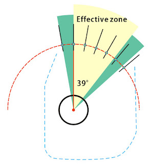
Draw lines across the orange curve, all lines radiate from pole center, distributed every 10°, these are the reference points. - According to the lens/ rangefinder measuring data, we now locate each reference point. Let's say while we measure the rangefinder, and find out the data as follows
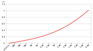
infinity 0
30m 0.04
15m 0.07
10m 0.1
8m 0.12
6m 0.16
4.5m 0.22
3.6m 0.28
3m 0.35
2.4m 0.44
1.8m 0.52
1.5m 0.6
1.2m 0.73
1.0m 0.88
0.9m 1.01
and the data was transfered into characteristic curve
Another data comes from measuring lens focus moving range
notice the y-axis in this chart, it transfer rail moving range(mm) into rotating degree, as rail moves within 20.5mm range and cam rotates within 39°, so even distributes two measurement, safely transfer two units.

find the focus distance at 10°, 20°, 30°, 39°, in chart above we get 4.45m, 2.4m, 1.7m and 1.35m. Then we back to the rangefinder chart, to locate 4.45m, 2.4m, 1.7m and 1.35m. we find that radius should add 0.24mm, 0.43mm, 0.56mm, 0.68mm accordingly. - Drag reference points on orange curve according data we just read out from charts, move them to proper distance to reflect the variations.

Then draw a smooth curve across all reference points,

- Enclose the curve with cam outline, make it a dedicated Geronar 6.3/150mm lens cam for 110B.

to compare new 150mm lens cam to original 127mm cam, you can tell the differences on outer curves. (orange curve: 127mm cam)


Thursday, June 23, 2011
Rangefinder calibrations on 110B- part4
Rangefinder
First system to be measured is RF parts.
We need to draw a rangefinder characteristic curve, to represent it's focus range. so there is a chart, focus distance in x-axis, and y-axis is the mirror moving range.
As we all agree, that Polaroid mass produced 110B cameras, so rangefinder part should represent same character in every camera body, but after measuring so many rangefinders, I found out that they all have their own characters. Maybe the camera was for 3x4 instant film, no image enlargement required, so it tolerates for range variety, but it is intolerable if we use this rangefinder on 5x4 camera.

Each rangefinder on Byron will be measure their characteristic curve individually, record and draw in chart, for further matching their prime lens.
To quick finish this tedious job, I managed to use a laser beam to do the focus, no need to peek all the time, thus won't hurt my eyes too much.
The measuring result will be something like this.
![]()
Lens
Lens measuring is simple and straightforward, you mount the lens on a 5x4 camera, set it focus at infinity, then define this location as zero point. As we already know that 110B rail has 20.5mm moving range, so we should find out the focus range this lens has in 20.5mm rail movement.
Stick a simple ruler at the side of the rail, and a pin as a pointer, now you can focus object at different distance and record the rail movement.
 The result should be as early post I made "Lens Curves".
First system to be measured is RF parts.
We need to draw a rangefinder characteristic curve, to represent it's focus range. so there is a chart, focus distance in x-axis, and y-axis is the mirror moving range.
As we all agree, that Polaroid mass produced 110B cameras, so rangefinder part should represent same character in every camera body, but after measuring so many rangefinders, I found out that they all have their own characters. Maybe the camera was for 3x4 instant film, no image enlargement required, so it tolerates for range variety, but it is intolerable if we use this rangefinder on 5x4 camera.
Each rangefinder on Byron will be measure their characteristic curve individually, record and draw in chart, for further matching their prime lens.
To quick finish this tedious job, I managed to use a laser beam to do the focus, no need to peek all the time, thus won't hurt my eyes too much.
The measuring result will be something like this.

Lens
Lens measuring is simple and straightforward, you mount the lens on a 5x4 camera, set it focus at infinity, then define this location as zero point. As we already know that 110B rail has 20.5mm moving range, so we should find out the focus range this lens has in 20.5mm rail movement.
Stick a simple ruler at the side of the rail, and a pin as a pointer, now you can focus object at different distance and record the rail movement.
Monday, June 20, 2011
Rangefinder calibrations on 110B- part3
So actually there are two focus systems, one by focus through lens, and one by focus through RF mirror.
Lens mount on front standard, from infinity to someplace near, limited by the moving range of camera rail, 110B rail got maximum moving range 20.5mm, for 150mm lens, it's about to 1.5m; for 127mm lens, about 1.0m; for 90mm lens, about 0.6m.
Rangefinder rotates mirror to adjust focus, by measuring 127mm lens cam, I found out that RF mirror rotates only 1mm to accomplish focus range from infinity to 1m.

How to synchronize lens and RF? that's what cam stands for. different lens needs different cam, cam with different outer curve. Outer curve comes from lens focal length. for 90mm lens, it can be set focus range from infinity to 0.6m, much wider than 127mm lens (i~1.0m) or 150mm lens (i~1.5m), so 90mm lens cam outer curvature steeper, 150mm lens cam outer curvature flatter.
Later I will show you how to synchronize two systems.
Lens mount on front standard, from infinity to someplace near, limited by the moving range of camera rail, 110B rail got maximum moving range 20.5mm, for 150mm lens, it's about to 1.5m; for 127mm lens, about 1.0m; for 90mm lens, about 0.6m.
Rangefinder rotates mirror to adjust focus, by measuring 127mm lens cam, I found out that RF mirror rotates only 1mm to accomplish focus range from infinity to 1m.

How to synchronize lens and RF? that's what cam stands for. different lens needs different cam, cam with different outer curve. Outer curve comes from lens focal length. for 90mm lens, it can be set focus range from infinity to 0.6m, much wider than 127mm lens (i~1.0m) or 150mm lens (i~1.5m), so 90mm lens cam outer curvature steeper, 150mm lens cam outer curvature flatter.
Later I will show you how to synchronize two systems.
Subscribe to:
Posts (Atom)